Hydraulic Speed Control Diagram Hydraulic Adjustable Variabl
Hydraulic control valve speed controlling circuits Winch hydraulics formulas terminology valve mfg loader relief directional valves Simplified hydraulic circuit schematic for the motor efficiency test
Speed Control of Hydraulic Cylinder | Internal Combustion Engine
Valve flow control hydraulic variable adjustable npt hydraulics fc51 gpm line Hydraulic circuit training animation drawing hydraulics valve control pressure industrial systems simple pump course ring relief snapshot build gauge piston Do you want to control the speed of a hydraulic motor or cylinder and
Circuit motor simplified piston efficiency valve directional
Speed control of hydraulic cylinderBrand hydraulics side-ported adjustable flow control valve — 3/4in. npt Control of a double-acting hydraulic cylinderUnderstanding a basic hydraulic circuit 01.
Hydraulic beginners cylinder electrical fluid fundamentals hydraulik electromechanical acting pnuematic let hidraulica hydraulics drawing pneumatic valves discuss mentionedHydraulic speed circuit control Loop hydraulic hydraulicspneumatics closingHydraulic cylinder acting double schematic valve control pump flow pressure way system oil troubleshooting four through circuits deactivated relief unless.

Valve control flow hydraulics adjustable brand gpm ported npt ports side model over sae northern 2in 4in northerntool hover zoom
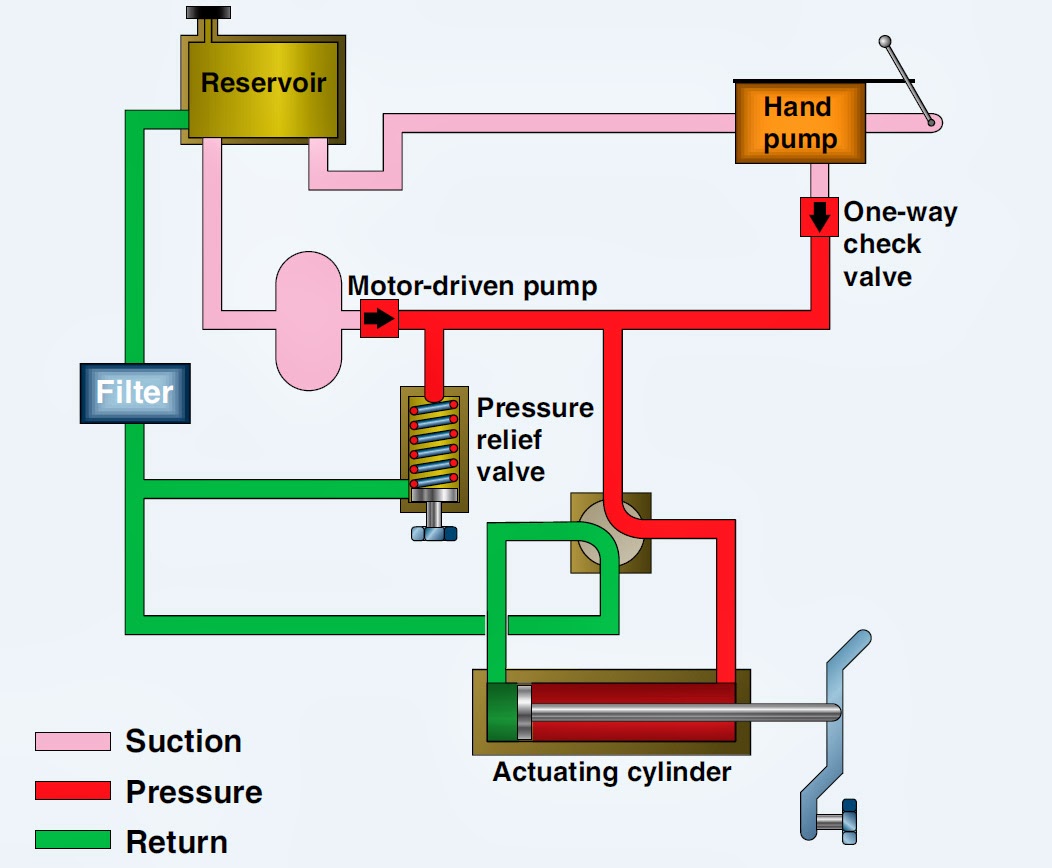
Hydraulic basic system aircraft systems power law diagram schematic gear control hydraulics examples pascal management components figure mechanical pascalsHolid industrial hydraulic speed controller ,hydraulic speed regulator Larsen lights, led lights for your equipment !. hydraulic control valveSimplified hydraulic circuit schematic for the motor efficiency test.
Speed controller hydraulic absorbersParker inline mounting hydraulic flow control valve, g 3/8, 210bar Hydraulic adjustable variable flow control valve, 0-30 gpm, 3/4” nptClosed-loop speed control of hydraulic motors.
The schematic diagram of hydraulic speed regulation systems in
Hydraulic valve control schematic directional equipment diagram flow cylinder motor pump acting double spring electric solenoid filter position reservoir variableHydraulic motor speed cylinder control diesel Industrial hydraulic circuit training with animation1 a pneumatic hydraulic speed control, for industrial at rs 32900/piece.
Hydraulic speed control system.Schematic diagram of an improved hydraulic drive with two-line control Hydraulic speed control feed hydro regulator drillHydraulic cylinder control speed schematic circuits circuit meter dcv retract when troubleshooting.

Speed control hydraulic circuit
Motor hydraulic control speed circuits torqueHydraulic cylinder speed control Speed control of a hydraulic motorHydraulic regulation schematic valve.
Hydraulic control valve speed controlling circuitsHydraulic speed control, drill feed control cylinders, hydro speed Engineering essentials: types of speed-control circuitsSpeed control of a hydraulic cylinder.

Aircraft systems: basic hydraulic systems
Hydraulic speed control experiment examplesHydraulic motor control speed variable displacement circuit bidirectional Speed control of hydraulic motorsBasic hydraulic system circuit diagram and working animation.
Hydraulic system for beginnersHydraulic schematic simplified pump directional rig piston through Directional control valveHydraulic speed control experiment.

Hydraulic speed regulators control dynamic loads
Hydraulics systems diagrams and formulas .
.


Hydraulic Adjustable Variable Flow Control Valve, 0-30 GPM, 3/4” NPT
Hydraulic Speed Control, Drill Feed Control Cylinders, Hydro Speed

Larsen Lights, LED lights for your equipment !. Hydraulic Control Valve

Aircraft systems: Basic Hydraulic Systems
Hydraulic cylinder speed control - YouTube

Speed Control of Hydraulic Cylinder | Internal Combustion Engine