Idss In Jfet Circuit Diagram Idss Fets Drain Current Gate Sh
Jfet transistor junction construction byjus Solved: a jfet circuit is shown in figure 1 below. the n-jfet has a Dss pinch
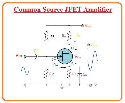
Explain the structure and working of JFET. : Electric guider
Idss test circuit for jfets and d-mosfets. with tutorial. Jfet circuit diagram Jfet idss please voltage
Jfet oscillator coupled
Jfet circuit diagramIdss fets drain current gate short source when amp Idss test circuit for jfets and d-mosfets. with tutorial.Jfet idss vgs given off.
Jfet j310 drain idss voltage zeroThe basic circuit of the source-coupled jfet oscillator. Idss in jfet circuit diagramWhat is, idss, of a fet transistor?.

Jfet idss matching – stompville
Solved the jfet in the circuit at right has an idss of 5 maSolved for jfet transistors idss =8ma,rd=∞, and vp=−6v Idss finder, idss values for fets, drop-down menus2n5457 n-channel jfet : datasheet, working & its applications.
Solved the jfet in the circuit of figure 3 has an idss ofIdss test circuit for jfets and d-mosfets. with tutorial. Electronics jfet idss explained using j310 gate zero voltage drainSolved: refer to the cascaded circuit below which uses identical jfet.

What is the output resistance of the self-biased jfet
Junction field-effect transistors (jfet): operation, characteristicsTransistor fet characteristics region saturation jfet channel idss transfer vgs drain field mosfet voltage cutoff ohmic breakdown transconductance fets transistors Idss finder, idss values for fets, drop-down menusIdss jfet transistor matching match.
Solved in the circuit below for jfet, find ie, ib & icSolved a jfet voltage amplifier has an idss = 10 ma, vp=-6v Answered: problem 3: in the circuit below, the…Solved the following jfet amplifier has an idss of 4.3 ma,.

Jfet explain
Solved the jfet transistor in circuit below has idss = 10Jfet circuit applications figure operation source channel configuration input common Solved if the jfet in the circuit to the right has idss=5 maJfet idss matching tester measured sample single over.
Jfet circuit diagramBurning amp ba-3 Jfet: junction field effect transistor construction and workingJfet circuit diagram.

Idss jfet operation zone mosfet fets red fig amp
Jfet circuit diagramExplain the structure and working of jfet. : electric guider .
.


Solved For JFET transistors IDSS =8mA,rd=∞, and Vp=−6V | Chegg.com

rf - How does one set the Q-point for a JFET cascode amplifier, and

SOLVED: Refer to the cascaded circuit below which uses identical JFET

JFET - Junction Field Effect Transistor, Basics Explained
jfet circuit diagram - IOT Wiring Diagram

Solved If the JFET in the circuit to the right has Idss=5 mA | Chegg.com

Explain the structure and working of JFET. : Electric guider